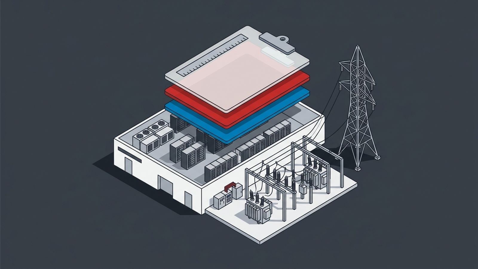


A motor runs at a lagging power factor because its current is delayed from the voltage. A capacitor runs at a leading power factor because its current comes earlier than the voltage (maker’s paper, p. 4). NERC says some large loads “are capacitive loads and operate at a leading power factor,” because their power electronics carry filters that also produce reactive power (NERC, p. 26). An IT power supply’s input filter capacitor draws the same leading current at any load, so the supply’s power factor falls as its load falls (maker’s paper, p. 5). A capacitor draws current 90 degrees ahead of the voltage (RUS bulletin, p. 13). When the capacitor rating exceeds the inductive load, the result is a leading power factor (RUS bulletin, p. 40).
What the NERC white paper says about large loads
The paper is the Large Loads Task Force white paper “Characteristics and Risks of Emerging Large Loads,” dated July 2025 (NERC).
Leading power factor. NERC says the active power electronics in these loads run at roughly unity displacement power factor and carry filters that also produce reactive power (NERC, p. 26). This can improve voltage regulation and reduce transmission losses, but it can worsen rotor angle stability (NERC, p. 26). Some of these filters are built into the power electronics, so they would not be visible in a single line diagram (NERC, p. 26, note 33).
Harmonics. NERC calls data centers a source of harmonics because of the power electronics in UPS units, power supplies and variable speed drives (NERC, p. 33). It says cooling systems contain drives, inverters and other equipment that “can create harmonics and increased reactive power demands” (NERC, p. 4).
Ramp rate. In one recording, a 50 MW block of a 200 MW AI training data center changed its demand at 1.9 p.u. per second for about 250 milliseconds (NERC, p. 6).
Oscillation. In 2023 a large data center in the Midwest produced a 1 Hz forced oscillation, after active power electronics at the site perturbed the system at one second intervals (NERC, p. 30).
What the paper does not say. It gives no power factor figure for a server rack and names no tariff penalty (NERC). It names capacitors in stability problems and capacitor switching in large load trips, but it does not discuss a capacitor bank as a power factor fix (NERC, pp. 32 and 36).
What a generator sees
NERC writes that most loads consume more reactive power than they produce, and generators supply much of it (NERC, p. 26). Loads that produce reactive power turn that around, and NERC files the result under generator reactive power absorption (NERC, p. 26). A synchronous generator absorbs reactive power by reducing its internal voltage, which raises its power transfer angle and cuts its angular stability margin (NERC, p. 26, note 34). Unless studies account for the excess reactive power, the stability margin may be overestimated, leading to field events where generators become unstable unexpectedly (NERC, p. 26).
A standby generator meets the racks directly when the UPS is in bypass or eco mode, or when a power path has no UPS (maker’s paper, p. 2). Leading current adds to the generator’s field, so its regulator cuts excitation until it can cut no further, and the generator then trips on overvoltage (maker’s paper, pp. 7 and 8). The paper’s general rule keeps leading reactive current below 20% of the generator’s maximum rated current (maker’s paper, p. 9). A Rural Utilities Service bulletin adds that a leading power factor can, in severe instances, make generators unstable, typically small isolated units (RUS bulletin, p. 40).
What correction has to do differently
A capacitor bank corrects the timing of the current and leaves its shape as it was (3DFS). A bank can also resonate with the supply at one harmonic and amplify it (3DFS). In one maker’s worked example, a 350 kvar bank on a 630 kVA transformer resonates at the 5.5th harmonic, next to the 5th a drive produces (3DFS). At a leading site a bank adds its own leading current to the leading current of the loads (RUS bulletin, pp. 13 and 40). The maker’s fixes work the other way. An inductive load bank supplies lagging current that cancels the leading current, and some active filters cancel leading current directly (maker’s paper, pp. 15 and 16).
Where 3DFS fits
The controller connects to the panel bus through its own breaker, beside the loads and never in the power path (3DFS). It supplies the reactive and harmonic current the loads draw, through the 23rd order, from its own terminals (3DFS). It corrects any timing error from a full quarter cycle of lag or lead down to none, capacitive or inductive (3DFS). It adds no capacitor bank, so the bank resonance above does not arise from it (3DFS).
Critical perspective
NERC’s Level 3 alert of 2026-05-04 asks planners to collect each computational load’s expected power factor, season by season (NERC Level 3 alert, p. 3). An expected value is a declaration, not a measurement. NERC notes that some filters are built into the power electronics and would not appear on a single line diagram (NERC white paper, p. 26, note 33). The final CLO-001-1 text does not use the words power factor or reactive power (CLO-001-1 final text). It leaves the modeling data list to each planning coordinator and its transmission planners (CLO-001-1, R8, p. 6).
One Texas utility’s tariff was written for the opposite problem. Oncor raises billing demand when power factor falls below 95% lagging at the meter (Oncor tariff, section 5.5.5, PDF p. 58). Its standard runs from unity to 95% lagging, and its billing formula names no charge for a leading reading (Oncor tariff, PDF p. 58). Oncor may correct a deviation and bill the customer only once it causes problems for other customers and notice fails (Oncor tariff, PDF p. 59). So the bill can stay quiet while the risk sits on the grid. NERC ranks angular stability as a high priority risk (NERC white paper, p. 38), and leading loads can worsen it (NERC white paper, p. 26).
One maker’s paper makes two points that cut both ways. A site may run correctly at first and develop the problem later as its IT equipment changes (maker’s paper, p. 2). A superficial analysis is likely to overstate the risk significantly (maker’s paper, p. 2).
A power factor figure without its sign is no basis for buying correction. Read the signed reactive current with the UPS in bypass, the condition the paper ties to generator trips (maker’s paper, p. 2). Read it again with the server supplies lightly loaded, where the paper says power factor gets worse (maker’s paper, p. 5). A capacitor quote built on an unsigned number answers the lagging clause in the tariff, not the leading condition at the site.
Questions
Can power factor be too high? No. Power factor is real power divided by apparent power (MIT OCW 6.622, Lecture 4, p. 2), and it always lies between 0 and 1 (maker’s paper, p. 3). A value such as 0.9 says nothing about the timing of the current, so it is written as 0.9 leading or 0.9 lagging (maker’s paper, p. 4).
Does a leading power factor cause a penalty? A Rural Utilities Service bulletin says most distribution utilities have clauses that encourage 90 to 95% power factor or charge a penalty (RUS bulletin, p. 40). It does not say how a tariff bills a leading reading, so the tariff wording decides (RUS bulletin, p. 40).
Do capacitor banks fix a leading power factor? No. A capacitor draws leading current, and when the capacitor rating exceeds the inductive load, the power factor goes leading (RUS bulletin, pp. 13 and 40). The bulletin’s fix for an excessively leading system is to reduce the capacitors or switch them off (RUS bulletin, p. 40).
What makes servers run more leading at light load? The input filter capacitor draws the same leading current at any load, so its share grows as the working current falls (maker’s paper, p. 5). The paper finds typical IT devices at 1 to 10 microfarads per kW of supply rating (maker’s paper, p. 10).