

At sea, thrusters, drives, reefers and sensors load the ship’s own generators with harmonic, reactive and unbalanced current that distorts the bus voltage and heats the generator. We correct that current at the panel, at sea and at the shore connection. We found no published figure for what poor power quality costs at sea.
Executive summary
The ship’s generator carries working current from corrected loads. We measure results against the vessel’s own baseline, so a pilot starts with an on-site network analysis. Our controller does not synchronize or convert frequency 23.
- At sea. Diesel generators feeding one switchboard. Correction at the panel leaves the generator balanced current at unity power factor. It delivers the same kilowatts with less current in its windings 17,21,23.
- Drives and thrusters. Loads that draw current in sharp pulses. Pulsed drive current bends the switchboard voltage more than on land, and correction at the panel supplies the harmonic share 1,17,23.
- Hybrid and battery ships. DC buses with inverters feeding AC loads. Reactive and harmonic current supplied at the load never passes through the inverter, so the battery pays conversion loss on working current only 27.
- At berth. Shore power through the port meter. The port meter charges the ship for the reactive share, and correction at the load panels on an AC ship raises the power factor the meter sees 20,21,23.
A ship makes its own electricity. A few diesel generators feed one main switchboard. Everything on board draws from the same bus: the thrusters, the pumps, the refrigerated containers, the lights, the radar and the computers 1. There is no utility behind the switchboard to absorb a problem.
Most of those loads now run on electronic drives and power supplies, which draw current in sharp pulses instead of smooth waves 1. A generator is a much weaker source than a shore transformer. So those pulses bend the voltage on the switchboard far more than they would on land 1,17.
Bent voltage heats generators and confuses their controls. It trips breakers and shortens the life of every motor and circuit board on the ship.
Software-Defined Electricity (SDE) fixes this at the panel where the loads sit. Our controller connects in parallel and measures the current a load draws. It supplies the useless part of that current itself, in millionths of a second 21,23.
- The rule. At every switchboard the currents add up to zero. Whatever the loads draw and nothing else supplies, the generator has to carry 21,22. Put a correction branch on the same bus, and the generator carries only the working current.
- A generator is a weak source. TM 5-689, a 2001 U.S. Army manual for land-based facilities, puts a standby generator at 5 to 100 times the sub-transient reactance of a shore transformer. By our arithmetic on that rule, the same distorted load makes 5 to 100 times the voltage distortion on board 17. Buying a bigger generator only halves the problem for double the money 17.
- Ships measure above the limits. A bow thruster on a standard drive ran at 12.6% voltage distortion. A chemical tanker averaged 11.5% 1,2. The class societies allow 8% and navies allow 5 8,12.
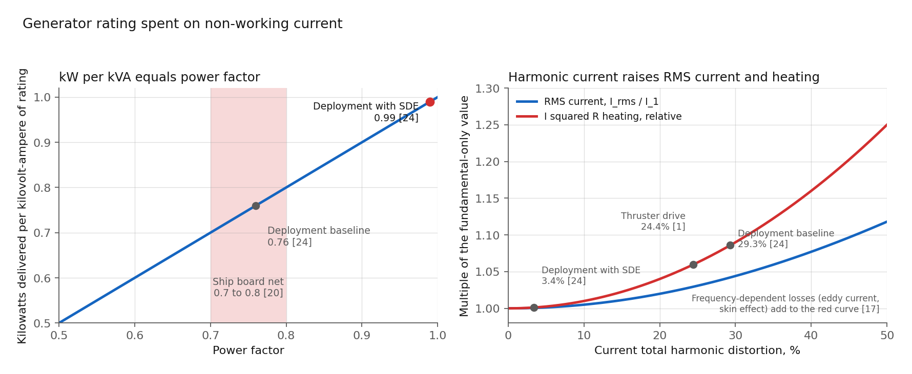
- In port, the ship becomes the port’s problem. A ship’s electrical system runs at a power factor of 0.7 to 0.8. The shore supply then has to deliver 25 to 43% more kilovolt-amperes than the ship’s working load, and ports charge for the difference 20. One cruise ship at berth draws 8 to 15 megawatts 19.
- A measured result. In our SDE deployment on refrigerated container operations, the controller moved power factor from 0.76 to 0.99. It cut current distortion from 29.3 to 3.4% and cut phase imbalance from 62 to 3.5% 24.
- Speed is the difference. A generator’s voltage regulator takes seconds to settle after a load step. A capacitor bank takes 1 to 3 seconds to switch 18,22. SDE corrects in under 100 millionths of a second, inside the first half cycle where the disturbance forms 22.
The problem
A ship at sea runs as an islanded grid 1. The sources on board are the only sources. A merchant ship’s generators feed a main switchboard at 400 or 440 volts 6, or at 6.6 kilovolts with step-down transformers to a 440 volt bus 15.
Thrusters, pumps and reefer (refrigerated container) sockets run at 440 volts three-phase. Lighting and electronics run at 230 or 115 volts through transformers off the same bus 6.
One rule governs the switchboard. Kirchhoff’s current law: the currents at a node sum to zero. Every ampere a load draws arrives from a source branch, on every phase and at every frequency 22. Reactive current, harmonic current and unbalanced current cross the same bus and the same generator windings as the real current. All of them spend the generator’s rating 17.
The generator turns current into voltage error. TM 5-689 states the mechanism. A given harmonic current makes less distortion on a low-impedance source and more on a high-impedance source 17. Correct the current at the panel and the switchboard voltage follows.
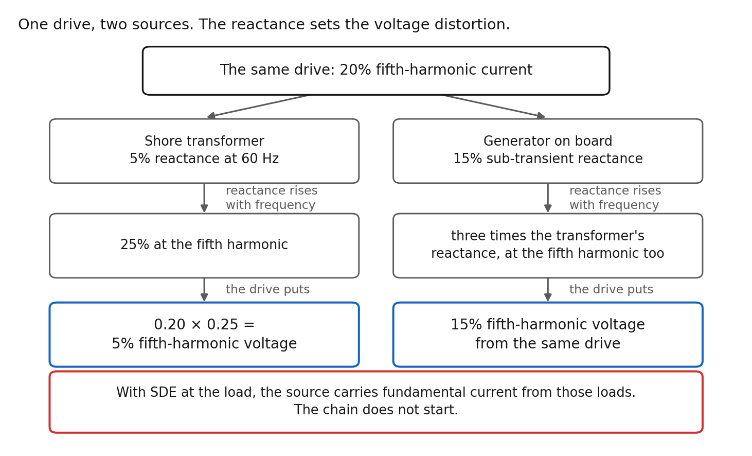
In an illustrative example, a drive runs at the full rating of its source. An ideal six-pulse drive draws fifth-harmonic current at 20% of its fundamental, and real drives without line reactors draw more 17. Inductive reactance rises with frequency, so a shore transformer with 5% reactance shows 25% at the fifth harmonic 17. The drive puts 0.20 × 0.25, or 5% fifth-harmonic voltage, on the transformer. A generator at 15% sub-transient reactance, three times the transformer, takes 15% from the same drive 17.
A drive at half the source rating makes half those figures. The arithmetic is linear and illustrative. Oversizing is a poor fix: halving the reactance takes a generator of twice the rating 17.
Ships measure where the arithmetic says they should. A 2021 review of maritime microgrids reports a bow thruster bus on a six-pulse drive at 12.6% voltage and 24.4% current distortion 1. The same review estimates a load-commutated propulsion converter without filters at up to 22% voltage distortion 1.
A chemical tanker with high-power converters averaged 11.5% voltage distortion up to the 50th harmonic, while a research vessel with active front-end drives held under 2% 2. An all-electric ferry peaked at 4.2% 1. Surveys on fifteen ships found power quality problems on four 3.

The limits are tighter than the measurements. IACS UR E24, ABS, DNV and Lloyd’s Register cap voltage distortion at 8% 8,9,10,11. ABS and DNV hold any single harmonic to 5%, and Lloyd’s Register holds orders above the 25th to 1.5%, measured to the 50th 8,9,10.
MIL-STD-1399 Section 300 holds naval 60 hertz power to 5% total and 3% per harmonic 12. User equipment of 1 kVA and above holds any single harmonic current to 3% up to 2 kilohertz 12. The system runs ungrounded. Leakage to the hull stays under 30 milliamperes per line 12.
IEEE 45-2002, since superseded, set 5% on a non-dedicated bus 14. Voltage tolerance is plus 6 to minus 10% steady state and plus or minus 20% for 1.5 seconds. Frequency tolerance is plus or minus 5% steady state and 10% for 5 seconds 8,9,13.
A small grid has no second chance. The National Transportation Safety Board (NTSB) report on the 2024 Dali blackout describes a 440 volt bus feeding lighting, steering gear pumps and main engine cooling pumps 15. The same bus fed the pump that was then supplying fuel to the running generators 15. The cause was a loose signal wire in a breaker’s undervoltage circuit, not a power quality event 15. The switchboard’s manual mode removed the 10 second automatic recovery 15.
The lesson is structural. Anything that degrades the bus degrades the ship: wiring, control settings or distorted current.
Signs the electricity on a ship is uncontrolled
- The switchboard monitor reads above 8% voltage distortion when a thruster runs 1,8.
- A generator trips on over-temperature while loaded under 70% of rating 17.
- The regulators hunt and the sets will not parallel onto a live bus.
- A capacitor in the harmonic filter room fails, and the ship blacks out.
- The port bill carries a reactive charge for a board net at 0.7 to 0.8 power factor 20.
- The reefer sockets run the phases at 62% imbalance 24.
Path one, today: generators, switchboards, filters and reactors
Yards build and protect most ships this way today. Diesel generators hold voltage and frequency. A power management system starts and synchronizes the sets and shares load between them 15,17. Drives feed thrusters, pumps and fans through six-pulse or twelve-pulse rectifiers 1. The yard adds line reactors, passive filters or phase-shifting transformers where the harmonic study demands them 1,8.
Generator heating and rating. Generator ratings assume undistorted 60 hertz current. Harmonic current raises hysteresis, eddy current and skin effect losses. Transformers and generators loaded to less than 70% of rating have shut down on over-temperature 17.
Reactive current spends rating too. A board net at 0.7 to 0.8 power factor converts only 70 to 80% of its generator’s kilovolt-amperes into kilowatts 20. The alternator’s current limit then arrives before the engine’s kilowatt limit.
Control instability. Voltage regulators, synchronizers, load-sharing controls and protection relays read voltage zero crossings and 60 hertz root-mean-square (RMS) current. Harmonics add zero crossings, regulators hunt, load sharing misreads, and paralleling becomes difficult or impossible 17. Every shore connection and every set closing onto a live bus is a paralleling event 20.
Resonance and the filter room. Passive filters and capacitor banks are analog compensation, tuned once for one network. Source inductance resonates with any capacitor bank at a harmonic frequency and amplifies the harmonic 17.
On 23 September 2010 a capacitor in the aft harmonic filter room of RMS Queen Mary 2 exploded. All four propulsion motors shut down within seconds and the ship blacked out 16. The MAIB found the likely causes were voltages above the capacitor’s rating and frequent voltage transients from switching, and the filter’s current-imbalance protection was not working 16.
Recovery time. ISO 8528-5 performance classes allow seconds of voltage and frequency recovery after a load step 18. A thruster start, a crane hoist or a compressor cycle lands inside the first half cycle, 8.3 thousandths of a second. The regulator is still settling from the first step when the second arrives.
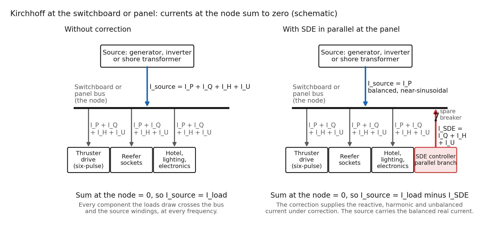
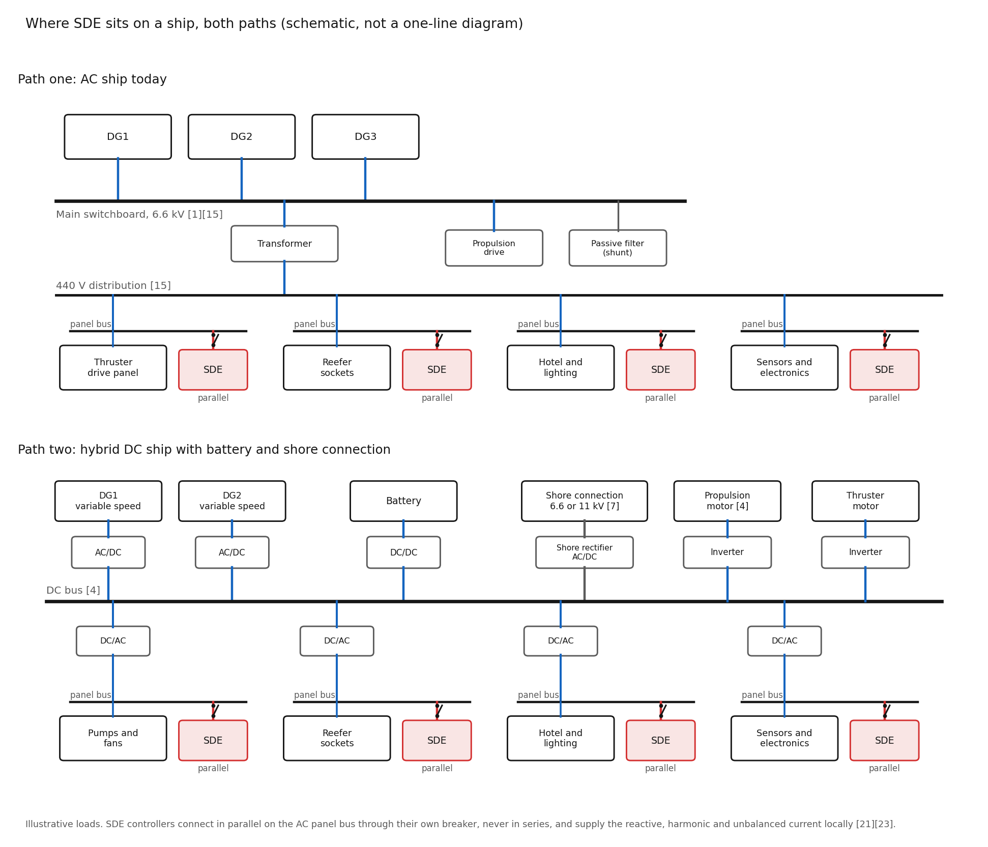
SDE’s role on this path. Our controller connects in parallel at the switchboard or the load panel through a spare breaker. It injects the reactive, harmonic and unbalanced share of the load current 21,23. By Kirchhoff, the generator branch carries the rest: balanced, near-sinusoidal current at unity power factor.
Below 0.8 power factor the alternator’s kVA limit arrives before the engine’s kilowatt limit, and correction moves the limit back to the engine. Windings carry 60 hertz current. Controls see clean zero crossings 17.
The filter room has less to filter. Six-pulse and twelve-pulse drives put most of their harmonic current at the 5th, 7th, 11th, 13th, 17th, 19th and 23rd 17. Harmonic elimination at the panel covers those orders 23.
Higher orders stay with the generator and the passive filter, and Lloyd’s Register limits those orders to 1.5% measured to the 50th 9. The switching sidebands of pulse-width modulated (PWM) drives sit above that range and need a line filter at the drive 3.
Path two, the future: hybrid propulsion, DC buses, batteries and shore power
New hybrid and electric ships increasingly use a DC bus 4,5. A DC bus lets each diesel run at variable speed, cutting fuel, noise and mechanical stress, and a battery on the same bus absorbs propulsion swings 5. Reviews describe DC shipboard microgrids as weak, with high-magnitude perturbations from propulsion 4. Every AC load still hangs on an inverter, and every generator feeds the bus through a rectifier 4.
One current budget. An inverter delivers about 1.1 to 1.5 times rated current, where a synchronous machine delivers about six times for several cycles 25,26. Real power, reactive support, harmonic cancellation and fault current all draw on the same budget 28.
A synchronous machine absorbs harmonic current through its sub-transient reactance, at the cost of the voltage distortion described above 17,28. An inverter absorbs harmonic current only within its current limit and its output filter’s range. A grid-forming inverter adds switching harmonics of its own 28. A ferry rebuilt around batteries trades a generator with a poor but real harmonic sink for a current-limited inverter with none to spare.
The inverter pays for every ampere. An AC load’s reactive and harmonic current circulates between the load and the inverter that feeds it. The inverter’s conduction and switching losses rise with its RMS output current, and RMS current includes the reactive and harmonic components 27. Those losses come off the DC bus and out of the battery.
Shore power. At berth the ship becomes a load on the port. IEC/IEEE 80005-1 covers high-voltage connection at 6.6 and 11 kilovolts for ships needing 1 MVA or more. IEC/IEEE 80005-3, published December 2025, covers 400 to 1,000 volt connections up to 1 MVA 7.
A 60 hertz ship on a 50 hertz port needs a static frequency converter 6,20.
The transfer itself is a synchronization: the last generator synchronizes to shore, the shore breaker closes, the generator offloads and stops, and departure reverses the sequence 20.

SDE’s role on this path. Reactive and harmonic current supplied at the load never passes through the inverter, the rectifier or the shore cable. The inverter’s current budget goes to real power and fault current 27.
Our controller does not depend on a network calculation. It measures the load current at the panel and supplies its non-working share at each instant 21,23. On an AC ship at berth, the port meter sees the ship’s load panels through the shore transformer. Correction at the panels therefore raises the power factor at the meter and cuts the harmonic current in the shore cable. On a DC ship the shore rectifier sets what the port meter sees, and SDE’s effect stays on the load side of each inverter.
Frequency conversion and synchronization stay with the shore converter and the power management system. The controller works downstream of the transfer. The corrected panels present balanced real current to the switchboard whichever source holds the bus: generator, shore transformer or both during the paralleled interval.
Why SDE is critical on both paths
A shore-power vendor states where correction on board works and where it does not. Compensation on board works where a static calculation is possible, and active compensation on board is problematic where the network construction varies a lot 20. That is the objection we answer here.
Software-Defined Electricity measures the full three-phase waveform at nanosecond resolution and corrects the current waveform digitally, at the load, at microsecond speed 21,23. The controller connects in parallel at the panel and sits outside the current path 23. Whether a generator, an inverter or a shore transformer holds the reference, the reactive, harmonic and unbalanced share of the corrected loads’ current stays at the load.
The node. I_gen = I_load minus I_SDE. Supply the non-working current at the panel and the source never carries non-working current from those loads 22.
Impedance. Voltage error equals current times source impedance at each frequency 17. Cleaning the current at the load is worth 5 to 100 times more on a ship than on a shore feeder.
Rating. Stator I²R loss falls with the square of the current 17. For the loads under correction, the harmonic reason for derating goes away 17. The engine still sets the kilowatt ceiling.
Speed. A regulator reacts to the voltage symptom: it begins to act in tens of milliseconds and settles over seconds 18. The error has formed, done its work on the controls, and gone before the regulator settles 22.
Phase balance. A 440 volt ship bus has three wires and no neutral. Unequal phase loading shows up as negative-sequence current 27. Negative-sequence current does no work and heats the generator rotor. MIL-STD-1399 limits line voltage unbalance to 3% 12. The controller injects the opposite negative-sequence current at the panel, so the generator sees three equal currents at 120 degrees 21. Hotel panels at 230 and 115 volts reach the bus through transformers, and balancing those panels balances the transformer primary too.
Controls and paralleling. The regulator, the synchronizer and the load-sharing controls see clean zero crossings, on every set closing onto a live bus and every shore transfer 17,20.
Protection. Lower RMS load current, with harmonics and reactive current removed, widens the gap between load level and trip level. Peak current on the container load fell 17 to 20% 24. The controller’s breaker and its fault contribution enter the ship’s protection coordination like any other inverter 8. Leakage to the hull is a separate quantity, and a marinized controller must meet the same 30 milliampere limit as any other user equipment 12.
Observability. Class rules require continuous harmonic monitoring with alarms at the main switchboard 8,11. Our controller adds a second record at the panel. It measures the full waveform of the loads under correction and logs each correction 23. The switchboard monitor shows the result. The panel record shows the cause.
On both paths, SDE gives the source a load worth its rating. We ship the VectorQ2 for 208 volt and the VectorQ5 for 480 volt networks, in production, in parallel at the panel 23. Controller count and rating follow the panel loads, and the network analysis sets both 23.
Start by measuring one switchboard before specifying a controller. Send the one-line diagram through the contact form and state the platform. We will say what we would measure and where.
This page sits under the Consumption pillar. Nonlinear loads produce waveform distortion, and a ship shows it with no utility behind the switchboard.
Four PQ Components pages carry the mechanisms this page leans on. Impedance Matching is why a generator is a weak source and what that does to the switchboard voltage. Harmonics is the drive current the generator has to absorb. Power Factor is the generator rating spent on current that does no work. Standards Compliance carries MIL-STD-1399 at the switchboard.
Sources
- Tarasiuk, T., Jayasinghe, S. G., Gorniak, M., Pilat, A., Shagar, V., Liu, W. and Guerrero, J. M. Review of Power Quality Issues in Maritime Microgrids. IEEE Access 9, 81798 to 81817 (2021). Open access. https://doi.org/10.1109/ACCESS.2021.3086000
- Tarasiuk, T., Jankowski, P., Shagar, V., Piłat, A., Górniak, M. and Nowak, J. Comparative Case Study on Oscillatory Behavior in Power Systems of Marine Vessels With High Power Converters. Frontiers in Energy Research 8 (2021). Open access. https://doi.org/10.3389/fenrg.2020.529756
- Mindykowski, J., Tarasiuk, T. and Gnaciński, P. Review of Legal Aspects of Electrical Power Quality in Ship Systems in the Wake of the Novelisation and Implementation of IACS Rules and Requirement. Energies 14(11), 3151 (2021). Open access. https://doi.org/10.3390/en14113151
- Xu, L., Guerrero, J. M., Lashab, A., Wei, B., Bazmohammadi, N., Vasquez, J. C. and Abusorrah, A. A Review of DC Shipboard Microgrids, Part I: Power Architectures, Energy Storage, and Power Converters. IEEE Transactions on Power Electronics 37(5), 5155 to 5172 (2022). https://doi.org/10.1109/TPEL.2021.3128417
- Radica, G., Vidović, T., Šimunović, J. and Jurić, Z. Overview of Hybrid Marine Energy System Configurations and System Component Modeling Approaches. Energies 18(5), 1189 (2025). Open access. https://doi.org/10.3390/en18051189
- Jesus, D., Oliveira, T., Perdigão, M. and Mendes, A. Plugging into Onshore Power Supply System Innovation: A Review from Standards and Patents to Port Deployment. Energies 18(20), 5449 (2025). Open access. https://doi.org/10.3390/en18205449
- IEC/IEEE 80005-1:2019, Utility connections in port, Part 1: High voltage shore connection (HVSC) systems, General requirements, edition 2.0 with AMD1:2022 and AMD2:2023 (6.6 kV and 11 kV systems, ships requiring 1 MVA or more). https://webstore.iec.ch/en/publication/29485. IEC/IEEE 80005-3:2025, Part 3: Low-voltage shore connection (LVSC) systems, edition 1.0, published 8 December 2025 (400 V to 1,000 V AC, 250 A and above, ships requiring up to 1 MVA). https://webstore.iec.ch/en/publication/30632
- ABS Rules for Building and Classing Marine Vessels, Part 4, January 2026: 4-8-2/7.21 (voltage THD not to exceed 8%, single order not to exceed 5%), 4-8-2/9.22 (continuous harmonic monitoring), 4-8-3/1.9 (voltage and frequency variations) and 4-8-5/5.3.5 (harmonic study and monitoring for electric propulsion). https://ww2.eagle.org/en/rules-and-resources/rules-and-guides.html
- Lloyd’s Register Rules and Regulations for the Classification of Ships, Part 6, Chapter 2, Section 1, paragraphs 1.8.2 to 1.8.4 (voltage and frequency variations, THD not to exceed 8%, harmonics above the 25th not to exceed 1.5%, measured to the 50th). https://www.lr.org/en/knowledge/lloyds-register-rules/
- DNV Rules for Classification, Ships, Part 4, Chapter 8, Electrical installations, Section 2 [1.2.7] (total voltage harmonic distortion not to exceed 8%, no single order above 5%). https://rules.dnv.com
- IACS Unified Requirement E24, Harmonic Distortion for Ship Electrical Distribution System including Harmonic Filters, Rev.1 (2018): THD not to exceed 8%, continuous monitoring for ships contracted on or after 1 July 2017. https://iacs.org.uk/resolutions/unified-requirements/ur-e
- MIL-STD-1399-300-1, Department of Defense Interface Standard, Section 300, Part 1: Low Voltage Electric Power, Alternating Current, 25 September 2018 (Type I 60 Hz power: voltage THD 5%, single harmonic 3%, line voltage unbalance 3%, voltage transient plus or minus 16% with 2 second recovery, ungrounded system, user equipment of 1 kVA and above limited to 3% single harmonic current to 2 kHz, line-to-ground leakage 30 mA per line). https://everyspec.com/MIL-STD/MIL-STD-1300-1399/MIL-STD-1399-SECT-300_PART-1_55833/
- IEC 60092-101:2018, Electrical installations in ships, Part 101: Definitions and general requirements, edition 5.0, clause 4.8 (power supply system characteristics), with the voltage and frequency variation table as reproduced in IACS UR E5 and the ABS and LR rules 8,9. https://webstore.iec.ch/en/publication/29989
- IEEE Std 45-2002, IEEE Recommended Practice for Electric Installations on Shipboard (voltage THD 5% and single harmonic 3% on a non-dedicated bus, 8% on a dedicated propulsion bus), as quoted in UK Maritime and Coastguard Agency MGN 449 (M), 2012. Current design part: IEEE Std 45.1-2023. https://standards.ieee.org/ieee/45.1/10718/ and https://assets.publishing.service.gov.uk/media/5a80d59140f0b62305b8d699/MGN_449.pdf
- National Transportation Safety Board. Contact of Containership Dali with the Francis Scott Key Bridge and Subsequent Bridge Collapse. Marine Investigation Report MIR-25-40, adopted 18 November 2025 (probable cause, low-voltage switchboard loads including the fuel oil flushing pump then supplying diesel generators 3 and 4, manual versus automatic recovery mode, power management system starting and synchronizing generators). https://www.ntsb.gov/investigations/AccidentReports/Reports/MIR2540.pdf. Preliminary report, 2024-05-14 (440 V bus, 6,600 V bus, transformers TR1 and TR2, breakers HR1 and LR1). https://www.ntsb.gov/investigations/Documents/DCA24MM031_PreliminaryReport%203.pdf
- Marine Accident Investigation Branch. Catastrophic failure of capacitor in aft harmonic filter room on passenger cruise ship RMS Queen Mary 2 off Barcelona, Spain, 23 September 2010. Report 28/2011. https://www.gov.uk/maib-reports/catastrophic-failure-of-capacitor-in-aft-harmonic-filter-room-on-passenger-cruise-ship-rms-queen-mary-2-off-barcelona-spain
- U.S. Army. TM 5-689, ADP/Computer Electrical Installation and Inspection for Command, Control, Communications, Computer, Intelligence, Surveillance, and Reconnaissance (C4ISR) Facilities. Headquarters, Department of the Army, 2001. Paragraphs 5-1 (harmonic amplitude 1/n), 5-2 (harmonic orders by pulse number), 5-4 (inductive reactance rises with frequency, capacitor resonance), 5-7 (derating, 70% over-temperature), 5-8 (generator control problems, load sharing, paralleling), 5-9 (E = I × Z, source impedance) and 6-4 (5 to 100 times sub-transient reactance, doubling rating halves reactance). https://www.wbdg.org/FFC/ARMYCOE/COETM/tm_5_689.pdf
- ISO 8528-5:2025, Reciprocating internal combustion engine driven alternating current generating sets, Part 5: Generating sets (performance classes G1 to G4, voltage and frequency recovery times of several seconds). https://www.iso.org/standard/85960.html
- Idso, S. K., Tuffner, F. K., Wang, D., Calkins, R. and Mammoli, A. Port Electrification Handbook: A reference to aid U.S. port energy transitions. PNNL-36016, Pacific Northwest National Laboratory, 2024 (shore power at 6.6 to 11 kV or 240 to 480 V, cruise ship at berth about 10 MW, port-reported 8 to 15 MW, motor inrush and generator trips). https://www.osti.gov/biblio/2479210
- Shore connection application document 9AKK107492A7830, 2019 (board net power factor 0.7 to 0.8, reactive energy charged at up to ten times the price of a kilowatt, 5 to 20 minute cable connection, synchronized transfer sequence, static frequency converter for 50 to 60 Hz, compensation on board where a static calculation is possible and active compensation on board problematic where network construction varies). Vendor brochure. https://search.abb.com/library/Download.aspx?DocumentID=9AKK107492A7830&LanguageCode=en&DocumentPartId=&Action=Launch
- 3DFS. Software-Defined Electricity: Optimized Electrification, Chapter 1 (nanosecond measurement, parallel installation without interrupting power, power factor, harmonic, phase balance and impedance correction, generators, backup power and microgrids named as the applications where impedance correction matters most). Company white paper. First-party. https://3dfs.com/sde-whitepaper
- 3DFS. SDE Technical Training Document (Kirchhoff’s current law at the node, correction current equals the negative of the harmonic, reactive and imbalance components, response-time comparison: SDE under 100 microseconds, active harmonic filter 1 to 10 ms, capacitor banks 1 to 3 s, automatic voltage regulator 1 to 10 s). Internal document. First-party.
- 3DFS. Products page (VectorQ2 and VectorQ5 in production, parallel connection at the panel, outside the current path, live measurement of the corrected circuit, pilot starts with an on-site network analysis) and SDE Summary page (the controller logs each correction). 3DFS website. First-party.
- 3DFS. SDE deployment on refrigerated container operations (refrigerated container on 460 V, 60 Hz, VectorQ5 in parallel on a 480 V panel, summary table: power factor 0.76 to 0.99, current THD 29.3 to 3.4%, phase imbalance 62.05 to 3.48%, peak current down 17 to 20%). Unpublished. First-party.
- Tuladhar, L. R. and Banerjee, K. Impact of the Penetration of Inverter-Based Systems on Grid Protection. CIGRE US National Committee, 2019 Grid of the Future Symposium (inverter-based resources generally produce fault current of 1.1 to 1.5 times rated output current). https://cigre-usnc.org/wp-content/uploads/2019/10/2D_3.pdf
- Keller, J. and Kroposki, B. Understanding Fault Characteristics of Inverter-Based Distributed Energy Resources. NREL/TP-550-46698, National Renewable Energy Laboratory, January 2010 (synchronous machines deliver about six times rated current for several cycles). https://www.nrel.gov/docs/fy10osti/46698.pdf
- IEEE Std 1459-2010, IEEE Standard Definitions for the Measurement of Electric Power Quantities Under Sinusoidal, Nonsinusoidal, Balanced, or Unbalanced Conditions (RMS current squared equals fundamental current squared plus harmonic current squared, with fundamental active and reactive components in quadrature, and positive, negative and zero sequence decomposition of unbalanced quantities). Superseded by IEEE Std 1459-2025. https://ieeexplore.ieee.org/document/5439063
- Porter, K. Watt-Logic. (a) Voltage, inertia and the Iberian blackout, part 1: the theory, 16 July 2025 (synchronous machines act as natural filters and harmonic sinks). https://watt-logic.com/2025/07/16/voltage-inertia-and-the-iberian-blackout-part-1-the-theory/ (b) Location, location, location: managing voltage in weak grids, 24 October 2025 (grid-forming inverters emit rather than dampen harmonics, all grid-forming functions draw on one limited current). https://watt-logic.com/2025/10/24/location-location-location-managing-voltage-in-weak-grids/
Version 2.0