
Command centers, radar sites, hospitals and water plants run electronic loads on a UPS, a generator or a battery. Uneven phases load the neutral and heat the backup source. We balance the current at the panel and record that the load stayed up. The Department of Defense reported 180 utility disruptions of 8 hours or longer in fiscal 2013, at about $220,000 per day, in data GAO calls incomplete 7.
Executive summary
From corrected panels, the UPS, generator and battery carry balanced working current. One controller corrects one panel. Correction at a load does not propagate back up the network. Pilots start with a network analysis measured against the facility’s own baseline 29,33.
- The neutral. Server, radio and radar power supplies. Supplying the third harmonic and the imbalance at the panel leaves the feeder neutral carrying near zero for those loads 27.
- Weak sources. Generators, UPS inverters and battery inverters. The same harmonic current makes more voltage distortion on a generator than on the utility transformer, in proportion to the source impedance 1.
- Standby generators. Days of island operation on a standby set. The alternator carries working current from the corrected panels, so its limit moves back to the engine 1.
- Battery islands. Installation microgrids on battery inverters. Current supplied at a bus-fed panel never passes through the battery inverter, so its budget goes to real power and fault current 20,22.
A command center runs on electronics. Servers, radios, radar processors and screens draw power through small converters. Those converters take current in short pulses. The pulses do not cancel where the three phases meet. The extra current returns on the neutral wire, heats transformers and confuses the controls on a standby generator.
The utility hides most of this. A generator does not. When the utility drops, the facility runs on a battery for minutes and on a generator for days. Every flaw in the load current then turns into a flaw in the voltage. The Army now plans for two weeks without the grid, the Navy for one.
Those weeks run on the weakest sources a facility owns. The load current decides whether they hold. This is the Consumption pillar at its plainest. Nonlinear loads distort the waveform, and a weak source turns that distortion into voltage error.
This is the gap Software-Defined Electricity (SDE) closes. Most power quality equipment reacts to a voltage symptom, in seconds, after the event. We measure the full waveform at the panel and correct the current at the load, digitally, inside the same cycle.
- The rule. The neutral carries what the three phases fail to cancel. Third-harmonic currents from the three phases arrive in the neutral in step and add up. TM 5-689 puts the theoretical neutral current of pulsed loads at least 1.73 and as much as 3.0 times the phase current 1.
- A generator is a weak source. TM 5-689 puts a standby generator at 5 to 100 times the sub-transient reactance of the utility transformer 1. The same manual sizes the generator at 1.6 times the UPS input kilowatts for a 6-pulse rectifier, to contain distortion 1. UFC 3-540-01 requires a harmonic analysis where switching power supplies reach 25% of the load 3.
- Loads measure above the limits. A UPS input measured about 12 to 15% total demand distortion across the three phases 10. Two server racks measured 6.4 and 13.2% current distortion before correction, and 1.9 and 3.6% after 30. IEEE 519-2022 sets 8% voltage distortion at the point of common coupling on buses of 1 kilovolt and below 9.
- Law and policy set the requirement. Federal law sets 99.9% availability for critical mission loads by the end of fiscal 2030 4. Army policy plans 14 days of energy and water for critical missions 3,5. The disruption record at the top of this page shows what each day without utility power costs.
- Tomorrow’s installation runs on batteries. Into a fault, an inverter delivers about 1.1 to 1.5 times its rated current. A synchronous generator delivers about six times for several cycles 20,21. Every ampere of reactive, harmonic or unbalanced current comes out of the same budget 22.
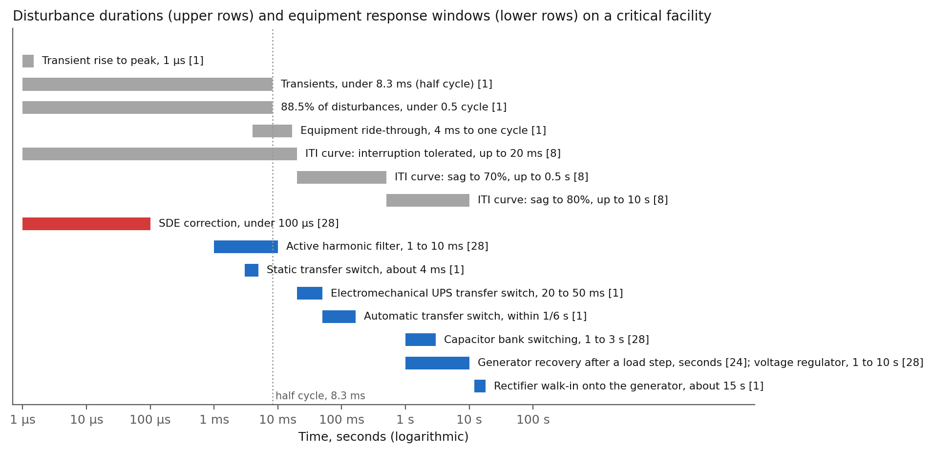
- Speed is the difference. Most power disturbances last under half a cycle, 8.3 thousandths of a second 1. Computer equipment tolerates a 20 thousandths of a second interruption 8. A static transfer switch needs about 4 thousandths 1. The VectorQ controller responds to a change in load current in under 100 millionths of a second 28.
The problem
A critical facility is an electronic load behind a UPS and a standby generator 1. TM 5-689 describes the load: data processing computers and their peripherals, telephone switching systems and electronic industrial control equipment 1. Radar antennas, pumps and air handlers sit on the mechanical side 1. Most computer equipment takes 208Y/120 volt power with a grounded neutral 1.
Each server draws current through a switching power supply, a major source of nonlinear load 1. Its pulses carry odd harmonics. Some of the pulsed current does not cancel in the neutral even when the three phases are carefully balanced 1.
Signs the electricity in a command center is uncontrolled
- The neutral runs warm on a conductor the balanced design assumed would carry nothing 1.
- A transformer or generator loaded under 70% of rating trips on over-temperature 1.
- The generator’s speed and frequency controls hunt, and the sets will not parallel, once the electronic load is on 1.
- The switchboard’s moving-iron meters read as much as 40% wrong on the same current 1.
- A load that ran fine on utility misbehaves on the generator set 1.
- A capacitor bank or tuned filter that was quiet on utility resonates at a harmonic frequency once the generator holds the bus 1.
- Ground-fault protection trips with no fault, because unbalanced current in the generator neutral moved the pickup 1.
- The UPS reads clean on its utility side and distorted on the critical panel behind the inverter 1.
One rule governs the neutral. Three balanced 60 hertz currents, 120 degrees apart, cancel in the neutral and add to zero 1. Third-harmonic currents do not cancel. For equal loads on the three phases, the three return currents at 180 hertz arrive in phase. The neutral carries their arithmetic sum, I_N = I_A3 + I_B3 + I_C3, or three times the third-harmonic current of one phase 1. The same holds for the 9th, 15th and 21st 1.
The same fact holds in the time domain. Each phase draws a short pulse. The six pulses per cycle land 60 degrees apart, and where none overlap, none cancel 1.
TM 5-689 puts the theoretical neutral current at least 1.73 and as much as 3.0 times the phase current 1. The 1.73 is the square root of three: non-overlapping pulses from three phases add in RMS as the root of the sum of squares 1,23. The 3.0 is the bound where all of the phase current is triplen 1.
Take an illustrative panel with 100 amperes of fundamental current on each phase and a third harmonic at 40%. The neutral carries 3 × 40, or 120 amperes at 180 hertz, on a conductor the balanced design assumed would carry nothing 1. The arithmetic is linear.
The design rules sit at the theoretical bound, not at the typical mix. UFC 3-520-01 sizes a shared neutral for at least 1.73 times the ampacity of the phase conductors 2. TM 5-689 recommends 200% 1.

Imbalance adds fundamental current to the same wire. A 120 volt load plugs into one phase. Unequal phase loading returns the difference on the neutral 26. In an older installation with a reduced neutral, the difference runs on the smaller conductor for hours 26.
UFC 3-520-01 limits design load imbalance to 5% 2. Computer manufacturers ask for no more than 5 to 20% load unbalance on any one phase and 2.5 to 5% voltage unbalance 1.
The same current heats everything upstream. Harmonic current raises hysteresis, eddy current and skin effect losses 1. Transformers and generators loaded to less than 70% of rating have shut down on over-temperature 1. Motors fed from distorted voltage draw harmonic current and overheat unless derated 1.
The cost arrives as lost insulation life. A 2020 motor study cites a temperature rise of about 4 to 6 degrees Celsius in induction motors from harmonics 17. A 10 degree rise halves insulation life 18.
The source turns current into voltage error. Voltage drop across the source equals current times source impedance 1. A given harmonic current makes less distortion on a low-impedance source and more on a high-impedance source 1. A UPS has high output impedance 1.
UPS makers specify output distortion under 5% and add the disclaimer “based on linear loads” 1. A modern UPS rectifier draws under 3% current distortion at full load and 5% at half load, at 0.98 power factor 1. The utility side of the UPS looks clean. The critical panel behind the inverter does not.
Nonlinear loads working fine on utility react entirely differently on a generator set 1.
Measurements land where the rules say. A 2024 study measured total demand distortion at a computer center’s UPS input at 11.95, 14.83 and 13.03% on the three phases 10. The authors report the UPS connection point over the 12% limit 10.
Our server rack assessment covered two racks on 120 volt phases 30. They measured 6.4 and 13.2% current distortion and power factor 0.931 and 0.831 30. Phase power spread ran from minus 39 to plus 40% on one rack and from plus 39 to minus 50% on the other 30. A 2026 survey of AI data centers estimates distortion from power-electronic loads at 8 to 10% 11.
A 2023 hardware demonstration built an emergency power system modeled on a 480 volt medical center 12. The island held, and the bus still bent. Voltage distortion on the islanded bus peaked at 6.3 to 6.8% across three test cases, against an 8% limit 12. IEEE 519-2022 sets 8% total and 5% per harmonic for voltage on buses of 1 kilovolt and below 9. TM 5-689 records computer manufacturers tolerating 3 to 5% voltage distortion with a linear load 1.

Path one, today: utility, UPS, generator and transfer switch
Most critical facilities run this way today and will for years. A service transformer feeds the building. Military facilities commonly load the service transformer to less than 25% at peak 2. An automatic transfer switch selects utility or a standby generator 1.
A double-conversion UPS carries the critical panels with a battery sized for about 15 minutes, the manual’s typical figure 1. The equipment room overheats within 15 to 30 minutes if ventilation stops 1. K-rated transformers, oversized neutrals and true-RMS relays handle the harmonics 1,2.
Sizing the generator. TM 5-689 sizes a standby generator for a UPS by the rectifier’s pulse number 1. A 6-pulse rectifier takes 1.6 times the UPS input kilowatts and a 12-pulse rectifier 1.4 times 1. The manual’s example sizes 408 kilowatts for a 255 kilowatt UPS input before other loads, and selects a 450 kilowatt set 1. For an insulated-gate bipolar transistor (IGBT) rectifier drawing under 5% distortion, the harmonic reason for the multiplier shrinks and step load sets the size 1.
UFC 3-540-01 holds generator sub-transient reactance to 0.12 where nonlinear loads reach 25%, and names data-processing equipment as the ISO 8528 class G4 case 3. Oversizing helps little. Halving the reactance takes a generator of twice the rating 1.
The transfer. On loss of utility the UPS goes to battery, the generator starts and stabilizes, and the transfer switch connects the generator to the UPS 1. The switch operates within one sixth of a second 1. The rectifier then walks load onto the generator over about 15 seconds 1.
Transients always accompany voltage outages 1. A motor reconnected 180 degrees out of phase draws 25 to 35% more inrush 1. TM 5-689 puts the resulting stresses at 156 to 183% above normal 1. With unbalanced loads, opening the neutral on a four-pole switch causes abnormal voltages for as long as 10 to 15 milliseconds 1.
Heating and control. Generator windings heat with the square of RMS current 1. Many regulators, governors and paralleling controls sense zero crossings 1. Heavy harmonic content adds zero crossings, and TM 5-689 records hunting in speed and frequency control and difficulty paralleling on such controls 1.
Load-sharing controls based on 60 hertz RMS give false readings with harmonics present 1. Moving-iron switchboard meters read as much as 40% wrong on harmonic current 1. UFC 3-520-01 now requires true-RMS sensing 2.
Filters and capacitors. Capacitor banks and passive filters are analog compensation. Each answers one condition 1.
Source inductance resonates with a power factor capacitor bank at a harmonic frequency. The resonance amplifies the harmonic, and the source no longer limits the current 1. TM 5-689 advises keeping capacitors off the line until the plant has observed generator operation with nonlinear loads 1.
A designer tunes a passive filter for one load and one source impedance 1. Changing the load, the source or the location degrades the filter’s performance 1. The generator is a different source. A filter designed against the utility impedance shares the harmonic current differently, and resonates at a different frequency, once the generator holds the bus 1.
SDE’s role on this path. The VectorQ controller connects in parallel at the 208Y/120 volt critical panel behind the UPS, or at the 480Y/277 volt mechanical panel 27,29. It sits beside the loads, not in their path 29. The connection runs through the controller’s own breaker with a three-phase, neutral and ground cable 27. The controller measures the current of the loads on the panel and supplies the reactive, harmonic and unbalanced share at each instant 26,27.
Correction through the 23rd harmonic covers the 3rd, 9th, 15th and 21st, the orders adding in the neutral 1,27. The same range covers the 5th, 7th, 11th, 13th, 17th and 19th, the orders a rectifier draws 1,27. Supply switching noise at 20 to 100 kilohertz, and orders above the 23rd, stay with each load’s input filter and the facility’s transient protection 1.
The feeder neutral from the corrected panel to its source carries near zero for those loads 27. Branch-circuit neutrals inside the panel are unchanged. The controller’s own neutral conductor carries the triplen sum and the imbalance current, and its rating sets the limit 27. In the worked example, a VectorQ2 rated 50 amperes per phase supplies the 40 amperes of third harmonic on each phase 27. Its neutral then carries the 120 ampere sum 27.
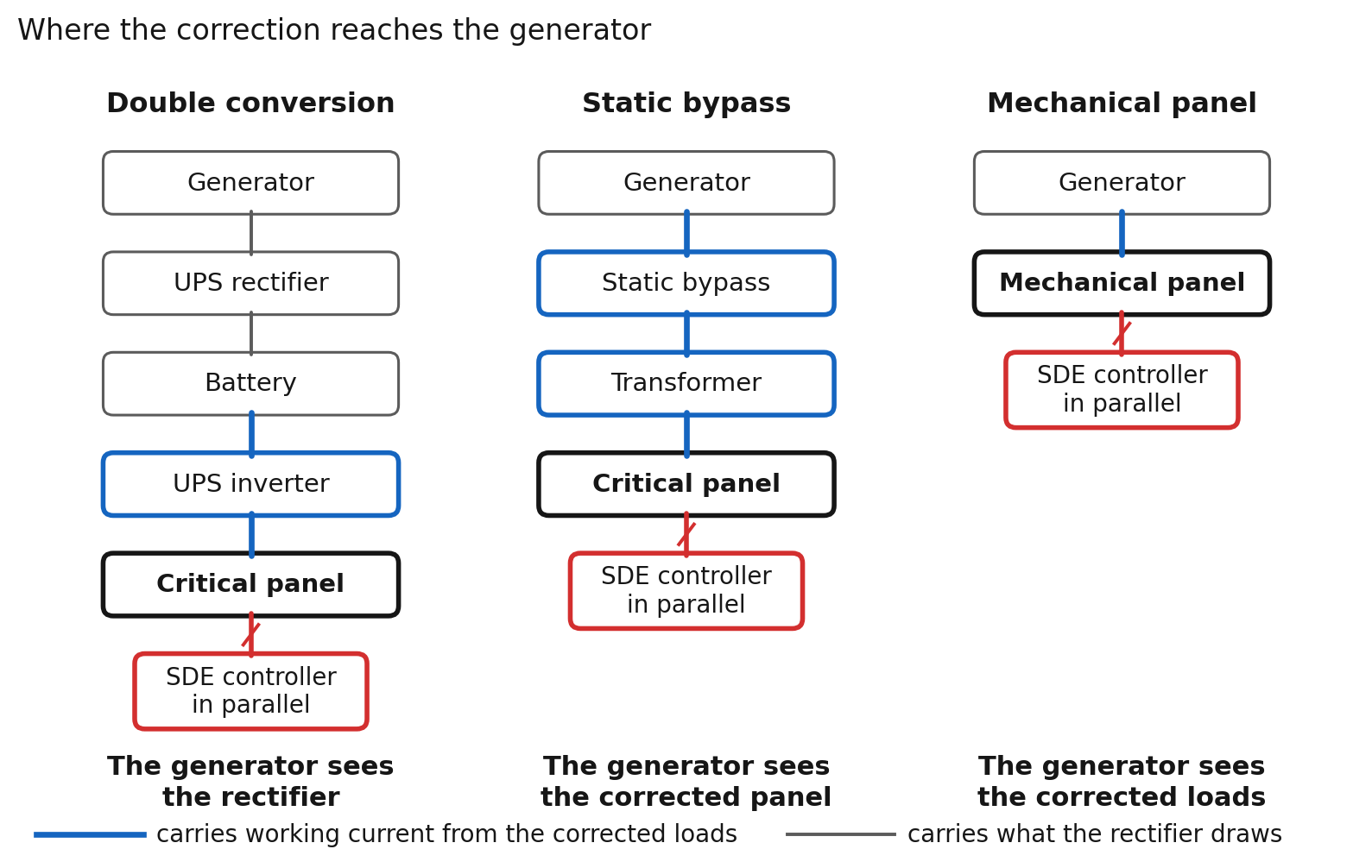
Where the correction reaches the generator depends on the UPS mode. In double conversion the generator feeds the rectifier, and the rectifier’s pulse number sets the 1.6 or 1.4 multiplier, whatever sits on the output panel 1. The corrected critical panel lightens the UPS inverter, which then carries balanced fundamental current from those loads. On static bypass the generator feeds the critical panel through the transformer, and there the corrected loads present balanced fundamental current 1.
On the mechanical panel the generator feeds the loads directly on both paths, so the correction reaches the generator at all times. Step load and motor starting still size the set 1. A shunt device on a UPS inverter output falls under the UPS maker’s application review, and the site network analysis records the UPS make and model 29.
The controller has an operating band. It is rated for plus or minus 15% on voltage and plus or minus 0.5% on frequency 27. We confirm behavior outside the band in the site network analysis. Through an open transition, a controller on a bus-fed panel loses power with the bus and restarts when the generator picks up the load. The restart runs a diagnostic 27.
The VectorQ2 is rated for 208 volt panels up to 60 kilowatts and 9 kilovolt-amperes reactive at 50 amperes per phase 27. The VectorQ5 covers 480 volt panels up to 120 kilowatts and 60 kilovolt-amperes reactive at 60 amperes per phase, with multiple units in parallel 27. The controller draws under 150 watts 27. Its losses reach 2.4 kilowatts on the VectorQ2 and 3.6 on the VectorQ5 at full correction, taken from the panel’s source 27.
Path two, the future: installation microgrids, batteries and fourteen-day islands
Military installations are moving the boundary of the island from the building to the base. Federal law now requires all of the critical mission load to reach 99.9% availability per fiscal year by the end of fiscal 2030 4. Standards by mission range up to 99.9999% 4.
Army Directive 2020-03 plans for 14 days of energy and water where the mission duration is not stipulated 3,5,16. The Navy generally requires 7 days of autonomy 13,14. UFC 3-540-01 requires 7 days of fuel on site or from a confirmed source 3. DoD policy requires available, reliable and quality power for missions 6.
The record explains the policy. The Department of Defense reported 180 utility disruptions of 8 hours or longer in fiscal 2013 at about $220,000 per day 7. Equipment failure caused 4,393 disruptions across fiscal 2009 to 2015 7.
The base as an island. Installations have historically relied on dedicated emergency diesel generators for critical loads 15. A 2021 Naval Postgraduate School study models an installation microgrid islanded for 14 days on two diesel generators, a photovoltaic array and a battery 13. The two generators share 5,000 gallons of fuel, enough for one week 13.
A 2022 follow-on found the first design short of generation with one generator out, shedding critical load for 15 of 336 hours 14. Loss of fuel supply shed load for 39 of 336 hours 14. The final design carried four 2.5 megawatt diesel generators, five photovoltaic arrays and five battery systems 14.
One current budget. The battery inverter is the weak source of this path. This is where the Generation pillar meets the page. The sources added to the base are inverters. Real power, reactive support, harmonic cancellation and fault current all draw on the same limited current 22.
A grid-forming inverter offers no low-impedance sink for harmonic current unless it is designed for one. A synchronous machine absorbs some 22. Cold load pickup after an outage concentrates reactive demand exactly when real power is also needed, and the inrush pushes inverters into current limiting 19. Critical loads such as hospitals, water treatment and communications come on first, when the island is smallest and the source is weakest 19.
A measured island. The 2023 demonstration modeled a 480 volt, 450 kilovolt-ampere medical center network 12. The island ran on a battery inverter, a generator and photovoltaics 12. The loads were 150 kilowatts and 72 kilovolt-amperes reactive of critical load, 60 and 30 of sub-critical, and 240 and 115 of non-critical 12. The demonstration held frequency within 0.5 hertz and voltage within 10% 12.
Take the paper’s own load numbers in an illustrative sum. The three classes total 450 kilowatts and 217 kilovolt-amperes reactive, so the sources supply about 500 kilovolt-amperes for 450 kilowatts of work 12. The paper’s classes are design allocations, not simultaneous measured demand 12.
Let the load panels supply the reactive share and the same island needs 450 kilovolt-amperes of source. By rating, four or more VectorQ5 controllers, one per panel of 120 kilowatts or less, supply the 217 kilovolt-amperes reactive 27. The arithmetic is linear and treats the paper’s figures as steady loads.

Fuel and the engine limit. The engine burns fuel for real power. The alternator’s limit is apparent power, and generator ratings assume 0.8 power factor 1. Below 0.8 the alternator’s current limit arrives before the engine’s kilowatt limit.
Reactive and harmonic current spend the rating without delivering work 1. A fourteen-day island with fuel as the binding constraint runs its generators near their limit 13,14. There each kilovolt-ampere of alternator rating counts.
SDE’s role on this path. Take a panel fed directly from the microgrid bus, the mechanical panel in Figure 5. Reactive, harmonic and unbalanced current supplied at such a panel never passes through the battery inverter, the generator or the photovoltaic inverter.
On the UPS-fed critical panel the correction lightens the UPS inverter, and the UPS rectifier presents its own near-unity current to the bus 1. Each corrected panel fed from the bus removes its own harmonic and reactive share from the bus voltage the photovoltaic inverter tracks and the paralleling controls sense 1,19. Panels without a controller keep theirs.
Grid-following inverters lose phase lock on a weak island, and a corrected panel takes its share of distortion off the bus they lock to 19. The controller runs with no internet dependency and corrects at the panel whether the base is on utility or islanded 29. The VectorQ controller does not form the island, dispatch the sources, hold frequency, supply real power, store energy, provide fault current, replace protection or replace the microgrid controller. SDE works below the island’s control layer, on the load panels, on either path.
Why SDE is critical on both paths
Software-Defined Electricity measures the full three-phase waveform at nanosecond resolution and corrects the current waveform digitally, at the load, at microsecond speed 26,28. The controller works on the current, inside the cycle, without interruption 28. The VectorQ controller samples the waveform 1,000 or more times per cycle 27.
Removing or powering down the controller leaves the panel as installed 27. Whatever holds the reference, the reactive, harmonic and unbalanced share of the corrected loads’ current stays at the panel. The controller’s surge protection is rated continuous and non-degrading, with no limit on event count 27.
The neutral. The neutral carries 3 × I_3 for each triplen order and the fundamental difference between phases, combined as the root of the sum of squares 1,23,26. In our rack assessment the phase power spread fell from minus 39 and plus 40% to within 1.4% of average on one rack 30. On the other rack the spread fell from plus 39 and minus 50% to within 1.6% 30. In an early two-day pilot on a 208 volt panel, before a demand step, the three phase currents spread 4.2 amperes uncorrected and 0.5 amperes corrected 31. The two events fell on separate days and are not a matched pair. The spread between phases is the comparison.
Impedance. The UPS inverter, the generator and the battery inverter all show higher impedance at harmonic frequencies than the utility transformer 1. Where the generator feeds the panel directly, the same harmonic ampere makes more voltage distortion on the generator than on the utility transformer 1.
Rating. RMS current squared equals the fundamental squared plus the harmonic squared, so every harmonic ampere adds heating without adding work 23. For the corrected loads, the transformer, the UPS inverter and the generator on bypass or on a direct-fed panel carry working current. Winding loss falls with the square of current 1. The harmonic reason for derating goes away for those loads 1. The engine still sets the kilowatt ceiling.
Speed. An IBM study cited in TM 5-689 classed 88.5% of power line disturbances as under half a cycle 1. Transients rise in 1 microsecond and last under 8.3 milliseconds 1. Manufacturers build 4 milliseconds to one cycle of ride-through into their equipment 1. A static transfer switch needs about 4 milliseconds and an electromechanical switch 20 to 50 1. A generator’s regulator reacts to the voltage symptom after it forms and recovers from a load step over seconds 1,24. The VectorQ controller responds to a change in the load current, a demand step, a reactive swing or a harmonic shift, in under 100 microseconds 28. Interruptions, sags and impulses on the source stay with the UPS, the transfer switches and the surge protection.
Phase balance. UFC 3-520-01 states that three-phase equipment loses rated capacity with voltage unbalance 2. The controller transfers the difference between phases at the panel 26,27. The specification states balance within 20% of average 27. Unbalanced current in the generator neutral alters ground-fault pickup and risks nuisance tripping 1. Balanced panels remove the cause.
Transfer. The corrected panel presents the same balanced fundamental current to whichever source holds the bus: utility, generator or both during a closed transition. The controller needs no configuration or parameter tuning for standard operation 27. A transfer changes how a passive filter shares the harmonic current 1. Reconnection, in-phase monitoring and neutral switching stay with the transfer switch.
Protection. UFC 3-520-01 specifies true-RMS sensing meters, relays and trip elements 2. Lower RMS load current, with harmonics and reactive current removed, widens the gap between load level and trip level. The controller’s breaker and fault contribution enter the coordination study like any other panel device. The controller is not compatible with residual-current or GFCI protective devices, and its touch current is limited to 3.5 milliamperes AC 27. On a panel with ground-fault protection the coordination study settles the arrangement.
Listing, environment and interfaces. The controller holds CE conformity assessment per IEC 62477-1 and UL compliance by field evaluation 27. The controller is an indoor, IP20 unit rated for minus 5 to plus 42 degrees Celsius, 85% humidity and 1,000 meters altitude, with Class A EMC 27. We build the controller in Pittsboro, North Carolina, with global components 27.
Observability. Standard power quality meters average over 10 or 12 cycles, about 200 milliseconds 25. Until 2022, federal law required DoD to report the number, location and financial effect of every utility outage of eight hours or longer 4. The controller measures the full waveform of the loads under correction and logs each correction, at the panel, where the disturbance forms 29. The switchboard monitor shows the result. The panel record supports the cause analysis.

On both paths, SDE gives the source feeding each corrected panel a load worth its rating. We ship the VectorQ2 for 208 volt and the VectorQ5 for 480 volt networks, in parallel at the panel 29. Both are in production 29. Controller count and rating follow the panel loads, and the network analysis sets both 29. A 2020 externally funded trial with an independent verifier sits on the public record 32.
Defense and critical infrastructure conversations start under the right agreements. Start with a one-week measurement at one panel before specifying a controller. Send us the facility type and the panel voltage through the contact form. We will say what we would measure and where.
Four PQ Components pages explain the mechanisms behind this page. Phase Balance is the neutral current and the motor heat. Resilience is the clocks of the mitigation stack and the margin between events. Impedance Matching is why a generator shows every ampere of distortion the utility hid. Standards Compliance carries MIL-STD-1399 beside IEEE 519.
Sources
- U.S. Army. TM 5-689, ADP/Computer Electrical Installation and Inspection for Command, Control, Communications, Computer, Intelligence, Surveillance, and Reconnaissance (C4ISR) Facilities. Headquarters, Department of the Army, 2001-09-10. Paragraphs 1-1 and 3-1 (facility types and loads), 2-3 e, f and i (transient rise time, transients with outages, disturbance types), 2-3 i(2) (IBM study, 88.5% under 0.5 cycle), 3-4 g (UPS output impedance, transfer switch times of 4 and 20 to 50 milliseconds), 4-6 b(2) (208Y/120 volt supply), 5-5 b(1), (11) and (12) (odd harmonics additive in the neutral, switching supplies at 20 to 100 kilohertz, switching supplies as a major nonlinear load), 5-6 a, c and d (neutral cancellation, triplen summation, 1.73 to 3.0 times), 5-7 c and d (70% over-temperature, motor derating), 5-8 b and c (zero crossings, load sharing), 5-9 a, b and c (E = I × Z, UPS output disclaimer, IGBT rectifier input), 5-11 b(3) (tuned filter sensitivity), 5-13 a (200% neutral), 6-1 b and Table 6-1 (ride-through, manufacturer tolerances), 6-4 and 6-4 a, c, d, f, g, h, i, l and n (battery time, walk-in, sizing multipliers, 408 kilowatt example, 5 to 100 times reactance, doubling rating, 0.8 power factor, winding heating, 40% meter error, capacitor caution), 6-6 e, f, i, j(1) and l (transfer time, inrush, motor loads including radar antennas and pumps, out-of-phase reconnection, neutral transfer and ground-fault pickup). https://www.wbdg.org/FFC/ARMYCOE/COETM/tm_5_689.pdf
- U.S. Department of Defense. UFC 3-520-01, Interior Electrical Systems, 2025-01-16, with Change 1, 2026-01-21. Paragraphs 3-2.12 (5% design load imbalance), 3-17 (harmonic mitigation for nonlinear loads), B-2.2 (rated capability reduced by voltage unbalance), B-4 (service transformers loaded under 25% at peak), B-5 (generator design for nonlinear loads, true RMS sensing) and B-6 (shared neutral ampacity 1.73 times phase conductors). https://www.wbdg.org/dod/ufc/ufc-3-520-01
- U.S. Department of Defense. UFC 3-540-01, Engine-Driven Generator Systems for Prime and Standby Power Applications, 2014-08-01, with Change 4, 2026-01-16. Paragraphs 2-3 (7 days of fuel, 14 days for Army secure critical missions per Army Directive 2020-03), 2-4.1.5 (harmonic analysis at 25% switching power supply load), 2-4.7.4 (ISO 8528 class G4, data-processing equipment), Table 2-2 (ISO 8528-5 recovery times) and D-2.3 (sub-transient reactance limited to 0.12 with 25% nonlinear load). https://www.wbdg.org/dod/ufc/ufc-3-540-01
- 10 U.S.C. 2920, Energy resilience and energy security measures on military installations, subsections (a)(1) and (a)(2) (99.9% availability of critical mission load by the end of fiscal 2030, standards from 99.9 to 99.9999% by mission), added by Pub. L. 116-283 section 316. 10 U.S.C. 2925, former subsection (a)(3) (details of commercial utility outages lasting eight hours or longer, including total number, location and financial impact), struck by Pub. L. 117-263 section 314(b)(1)(B), 2022. https://www.law.cornell.edu/uscode/text/10/2920 and https://www.law.cornell.edu/uscode/text/10/2925
- U.S. Army. Army Directive 2020-03, Installation Energy and Water Resilience Policy, 2020, as quoted in UFC 3-540-01 Change 4 paragraph 2-3 3 and in PNNL-38494 page 14 16 (“the Army will plan to sustain energy and water for a minimum of 14 days”).
- U.S. Department of Defense. DoDI 4170.11, Installation Energy Management, 2009-12-11, incorporating Change 2, 2018-08-31, Enclosure 3 paragraph 3.c (“plan and have the capability to ensure available, reliable, and quality power to continuously accomplish DoD missions”). https://www.esd.whs.mil/Portals/54/Documents/DD/issuances/dodi/417011p.pdf
- U.S. Government Accountability Office. GAO-15-749, Defense Infrastructure: Improvements in DOD Reporting and Cybersecurity Implementation Needed to Enhance Utility Resilience Planning, 2015-07-23 (180 utility disruptions of 8 hours or longer, about 220,000 dollars per day, fiscal 2013). https://www.gao.gov/products/gao-15-749. GAO-17-27, Defense Infrastructure: Actions Needed to Strengthen Utility Resilience Planning, 2016-11-14 (4,393 disruptions from equipment failure, fiscal 2009 to 2015). https://www.gao.gov/products/gao-17-27
- Information Technology Industry Council, Technical Committee 3. ITI (CBEMA) Curve Application Note, revised 2000. Sections 3.1 (plus or minus 10%), 3.5 (sags to 80% for 10 seconds, 70% for 0.5 seconds) and 3.6 (interruption up to 20 milliseconds). https://www.itic.org/resources/Oct2000Curve-UPDATED.doc
- IEEE Std 519-2022, IEEE Standard for Harmonic Control in Electric Power Systems, Table 1 (voltage distortion limits at the point of common coupling for buses of 1 kilovolt and below: 5.0% individual, 8.0% total). Active. Standard text paywalled. Values as reproduced by secondary sources and as applied in 12. https://standards.ieee.org/ieee/519/10677/
- Alawasa, K. M. and Al-Badi, A. H. Investigation and Analysis of the Power Quality in an Academic Institution’s Electrical Distribution System. Energies 17(16), 3998 (2024). Section 3.2.2 (UPS connection point, total demand distortion 11.95, 14.83 and 13.03% on phases A, B and C against a 12% limit, connection point reported over the limit). Open access. https://doi.org/10.3390/en17163998
- Ginzburg-Ganz, E., Lifshits, P., Machlev, R., Belikov, J., Krieger, Z. and Levron, Y. Technical Challenges of AI Data Center Integration into Power Grids: A Survey. Energies 19(1), 137 (2026). Section 3.3, Figure 13 (harmonic distortion from power-electronic loads, THD about 8 to 10%, survey estimate). Open access. https://doi.org/10.3390/en19010137
- Chakraborty, S., Park, J., Saraswat, G., Meyers, T., Wang, J., Tiwari, S., Khatana, V., Maqsood, A., Somani, A. and Salapaka, M. V. Emergency Power Supply System for Critical Infrastructures: Design and Large Scale Hardware Demonstration. IEEE Access 11 (2023). Abstract (480 volt, 450 kilovolt-ampere test system based on the network of a commercial-scale medical center, frequency within 0.5 hertz, voltage within 10%), power quality limits table (voltage THD 8%, individual 5%, Table 3 in the author version), hardware-in-the-loop results table (maximum THD 6.3, 6.8 and 6.7% by test case, Table 5) and the test system loads (150 kW and 72 kVAr critical, 60 kW and 30 kVAr sub-critical, 240 kW and 115 kVAr non-critical). Open access. https://doi.org/10.1109/ACCESS.2023.3325198
- Peterson, C. J., Van Bossuyt, D. L., Giachetti, R. E. and Oriti, G. Analyzing Mission Impact of Military Installations Microgrid for Resilience. Systems 9(3), 69 (2021). Section 2 (Navy 7 days of autonomy per UFC 3-540-01, Army 14 days), section 4 (two diesel generators sharing 5,000 gallons of fuel for one week, a photovoltaic array and a battery, 14 day island). Open access. https://doi.org/10.3390/systems9030069
- Mallery, J., Van Bossuyt, D. L. and Pollman, A. Defense Installation Energy Resilience for Changing Operational Requirements. Designs 6(2), 28 (2022). Section 2.2 (Navy 7 days, Army and Marine Corps up to 14 days), section 4.4 (critical load shed 15 of 336 hours with one generator out, fuel loss 39 of 336 hours, final design of four 2.5 MW diesel generators, five PV arrays and five battery systems). Open access. https://doi.org/10.3390/designs6020028
- Anuat, E., Van Bossuyt, D. L. and Pollman, A. Energy Resilience Impact of Supply Chain Network Disruption to Military Microgrids. Infrastructures 7(1), 4 (2022). Section 2.1 (installations have historically relied on dedicated emergency diesel generators for critical loads). Open access. https://doi.org/10.3390/infrastructures7010004
- Hoffman, M., Cruz, J., Kerby, J., Siddiqui, A., Tan, W. and De La Rosa, S. Microgrid Handbook for Army Resilience: A Technical Review. PNNL-38494, Pacific Northwest National Laboratory, 2025-10, page 14 (Army Directive 2020-03, minimum of 14 days). https://www.pnnl.gov/main/publications/external/technical_reports/PNNL-38494.pdf
- Muñoz Tabora, J., de Lima Tostes, M. E., Ortiz de Matos, E., Mota Soares, T. and Bezerra, U. H. Voltage Harmonic Impacts on Electric Motors: A Comparison between IE2, IE3 and IE4 Induction Motor Classes. Energies 13(13), 3333 (2020). Introduction (temperature rise of induction motors due to harmonics approximately 4 to 6 degrees Celsius, citing the paper’s reference 36). Open access. https://doi.org/10.3390/en13133333
- Zhang, J., Wang, J., Li, H., Zhang, Q., He, X., Meng, C., Huang, X., Fang, Y. and Wu, J. A Review of Reliability Assessment and Lifetime Prediction Methods for Electrical Machine Insulation Under Thermal Aging. Energies 18(3), 576 (2025). Introduction (a 10 degree Celsius rise corresponds to a 50% reduction in insulation lifetime). Open access. https://doi.org/10.3390/en18030576
- Shi, W., Bai, C. and Wang, Z. Power distribution system blackstart restoration using renewable energy. Nature Communications 17, 8498 (2026). Critical load classes energized first under limited supply, cold load pickup inrush with substantial reactive demand forcing inverters into current limiting, grid-following units losing phase lock on weak islands. https://doi.org/10.1038/s41467-026-76692-0
- Tuladhar, L. R. and Banerjee, K. Impact of the Penetration of Inverter-Based Systems on Grid Protection. CIGRE US National Committee, 2019 Grid of the Future Symposium (inverter fault current 1.1 to 1.5 times rated output current). https://cigre-usnc.org/wp-content/uploads/2019/10/2D_3.pdf
- Keller, J. and Kroposki, B. Understanding Fault Characteristics of Inverter-Based Distributed Energy Resources. NREL/TP-550-46698, National Renewable Energy Laboratory, 2010-01 (synchronous machines deliver about six times rated current for several cycles). https://www.nrel.gov/docs/fy10osti/46698.pdf
- Porter, K. Location, location, location: managing voltage in weak grids. Watt-Logic, 2025-10-24 (grid-forming inverters typically emit rather than dampen harmonics, synchronous generators act as a sink for some harmonics, all grid-forming functions draw on one limited current). https://watt-logic.com/2025/10/24/location-location-location-managing-voltage-in-weak-grids/
- IEEE Std 1459-2010, IEEE Standard Definitions for the Measurement of Electric Power Quantities Under Sinusoidal, Nonsinusoidal, Balanced, or Unbalanced Conditions, clause 3.1.2 (RMS current squared equals fundamental current squared plus harmonic current squared). Superseded by IEEE Std 1459-2025, clause unchanged in substance. The IEEE page at the URL is the 2025 edition. https://standards.ieee.org/ieee/1459/7578/
- ISO 8528-5:2025, Reciprocating internal combustion engine driven alternating current generating sets, Part 5: Generating sets (performance classes G1 to G4, voltage and frequency recovery times of several seconds after a load step, as reproduced in UFC 3-540-01 Table 2-2 3). Edition 6, 2025-05, superseding the withdrawn 2022 edition. https://www.iso.org/standard/85960.html
- IEC 61000-4-30:2025, Electromagnetic compatibility (EMC), Part 4-30: Testing and measurement techniques, Power quality measurement methods, edition 4.0 (class A basic measurement interval of 10 cycles at 50 hertz or 12 cycles at 60 hertz). https://webstore.iec.ch/en/publication/71611
- 3DFS. Software-Defined Electricity: Optimized Electrification, Chapter 1 (Kirchhoff’s current law and neutral current from unbalanced phases, nanosecond measurement, parallel installation without interrupting power, power factor, harmonic, phase balance and impedance correction, communication systems and generator backup named among the applications). Company white paper. First-party. https://3dfs.com/sde-whitepaper
- 3DFS. VectorQ Technical Overview, Installation and Application Notes, current revision (VectorQ2 208 volt, up to 60 kW, 9 kVAR, 50 A per phase. VectorQ5 480 volt, up to 120 kW, 60 kVAR, 60 A per phase. Voltage tolerance plus or minus 15%, frequency tolerance plus or minus 0.5%. Harmonic measurement to the 53rd order and correction to the 23rd. Neutral current reduced to near zero by active phase balancing. Phase load balancing within 20% of average. 1,000 or more samples per sine wave. Heat dissipation under 2.4 kW and 3.6 kW at full load. Connection by a three-line, neutral and ground cable in parallel to the network. Multiple units in parallel. No configuration or parameter tuning for standard operation. Diagnostic of about three minutes at power-on. Not compatible with RCD or GFCI devices. Touch current 3.5 mA AC. CE conformity assessment per IEC 62477-1, UL compliance by field evaluation. Indoor, IP20, minus 5 to plus 42 degrees Celsius, 85% humidity, 1,000 m altitude, EMC Class A. Manufactured in Pittsboro, North Carolina with global components. The electrical system continues to operate as before if the controller is removed or powered down). Product document. First-party.
- 3DFS. SDE Technical Training Document (response-time comparison: SDE under 100 microseconds, active harmonic filter 1 to 10 milliseconds, capacitor banks 1 to 3 seconds, automatic voltage regulator 1 to 10 seconds. Correction current equals the negative of the harmonic, reactive and imbalance components). Internal document. First-party.
- 3DFS. Products page (VectorQ2 and VectorQ5 in production, parallel connection at the panel, outside the current path, installation without interrupting the circuit, live record of power quality at the panel, pilot starts with an on-site network analysis), SDE Summary page (the controller logs each correction) and Resilience page (the controller works at the grid edge with no internet dependency and no cloud latency). 3DFS website. First-party. /products, /technology/sde-summary and /technology/resilience
- 3DFS. Electrical network analysis of server racks at a data center, redacted field report, summary table (VectorQ2a in parallel on two server racks at about 120 volts per phase and about 2 kilowatts each, installed in about 20 minutes without interrupting power. Rack 1 current THD 6.4 to 1.9%, power factor 0.931 to 0.999, phase power spread minus 1.00, minus 39.06 and plus 40.06% to plus 1.35, minus 0.93 and minus 0.42%. Rack 2 current THD 13.2 to 3.6%, power factor 0.831 to 0.995, phase spread plus 38.65, plus 11.20 and minus 49.85% to minus 0.64, plus 1.52 and minus 0.88%). Redacted site assessment. First-party.
- 3DFS. Images and Brief Assessment from an early pilot project (VectorQ2 on a three-phase 208 volt panel. Phase currents before a demand step, uncorrected: 12.6, 12.1 and 16.3 amperes. Corrected, on a following run: 14.8, 14.3 and 14.6 amperes). Unpublished pilot record, site and date withheld. First-party.
- UK Ministry of Defence. Sanctuary Awards 2020, Highly Commended, Energy, Low Carbon and Resource Efficiency: The Defence Innovation Software Defined Electricity Project, published 2021-03-16 (trials in 2020-02 at the 3DFS facility in North Carolina, funded by the Defence Innovation Unit, with Underwriters Laboratories as independent third party. The entry states neutral current reduction to a negligible level. The entry states the technology had not been industrially deployed at any scale and names the MOD as the only external organisation to have tested the technology). GOV.UK. https://www.gov.uk/government/publications/mods-sanctuary-awards-winners-2020/full-list-of-the-sanctuary-award-winners-2020. The results and caveats are on the Press and Proof page.
- Army Technology, 2021-04-01, reprint of the Brite Innovation Review interview with Lt Cdr Jonathan Parker, UK MOD Defence Innovation Unit (the 2020 test: correcting at the main power board in an industrial unit does not necessarily propagate down to the last distribution board, and correcting at the last load does not propagate back up the network). https://www.army-technology.com/features/current-challenges-how-ai-enabled-power-distribution-could-prevent-losses/
Version 3.0